Friday, October 28, 2005

FF ( Fast Forward)


Not much progress this week due to work & domestic "stuff".
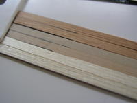
While I am waiting for the deck timbers to arrive, I am "fast forwarding" to a few sub assemblies.

Actually leapt from section 8 to section 22 in the instructions !

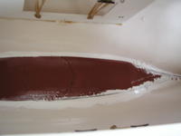
Firstly the anchor winch assembly, this is a balsa block that needs shaping & sanding, then various small parts are added to complete the assembly.

Personally, I didn't like the look of the main balsa anchor housing, so I cladded it with very thin plasticard and filler as necessary, this gave me a much smoother finish. Sprayed with white primer it looks fit for purpose.. I haven't decided if I shall keep it white or paint another colour.


I have also made a start on the deck spinnakers..... these are shaped dowels that need further attention,in form of sanding to shape..... (Does seem a little odd to me, as one end of each dowel is already shaped, yet the other end the modeller has to do ?)

I used a "surform" tool to take off the bulk of the wood, before hand sanding to the final shape. This photo clearly shows the difference between the two ends !

Wednesday, October 19, 2005

Decision on planking

Well, after a small straw poll amongst my pals, the overall wood of preference was the Honduran Mahogany.

However, after sitting and looking at my test samples, I have decided to "buck the trend" and go for the Lemonwood as the main planking material !

It is about 50% darker than the Robbe planks supplied, and I feel, the light deck and the darker mahogany superstructure will contrast & look nicer, rather than all dark wood.

In the end, it's ones personal choice /decision, and I am happy with that decision.
Needless to say Keith at Modelling Timbers has got my order, as their quality & service is truly excellent.

Approximately 3/4 weeks to delivery, as each plank is individually cut and machined to order.
So I may look further into the instructions and continue with a sub assembly or two !

Monday, October 17, 2005

Samples Arrived

Well, true to his word, Keith at Modelling Timbers, delivered, my samples of Lemon wood and Honduran Mahogany. ( thanks Keith :)

The quality of these timbers & machining is truly excellent..... I regret to say, having seen these, the Robbe planks are destined for the scraps box or paint stirrers !

These two woods are simply fantastic quality.

Above shows from front to back, robbe kit planks, Lemonwood, Honduran Mahogany, all in their natural state.

Cutting & gluing them to plasticard with long edges "marked", after one sanding operation and one coat of robbe wood wax, they look like this.......


Now, I have the dilemma, both are such lovely timbers, I don't know which I prefer !

I am also experimenting further with the caulking method, as advised by Keith at Modelling Timbers, now I have 200 of robbe planks to play with ! (Sorry Robbe!)

Once I make my decision, I shall place my order with Keith.... a small straw poll among my pals, shows their favourite is the Honduran Mahogany, which does have a warm feeling in its colour! !


Watch this space for my final decision and progress !

Sunday, October 16, 2005

A Discovery !

Purely by chance I have discovered this wonderful web site

http://www.modellingtimbers.co.uk

Keith Jewell is the proprietor,and what a helpful guy he really is.
He will bespoke cut his 1st quality timbers to your requirements, at no extra charge.

His web site is a mine of information, of interest to all modellers, looking to purchase the finest quality timber for their projects.

As you are aware, I have been looking for something "better" for planking my Atlantis deck, rather than use the supplied planks from the kit.

Modelling timbers offers a superb pre-sales service, backed up with excellent advice, knowledge and top class products.

True "top notch "service, so rarely seen these day :)

They are sending me samples of 2 types of wood he recommends... and once I have possession of these and made my decision, he is sure to get my order !

Interestingly, Keith ( being a timber expert) concurs with Robbe's recommendation of waxing the deck, ( NOT VARNISHING). I for one, will be accepting his advice :)

Do take a good look at his web site, you will have a "voyage of discovery".... trust me .

Saturday, October 15, 2005

Size Matters !

Just in case anyone has no idea just how big this project really is ..... Check this out !


Photo courtesy of SMG Isar-Piraten Posted by Picasa

Thursday, October 13, 2005

Initial Plank Tests


While waiting delivery of some differing types of wood plank, I have been "testing" the supplied robbe planks.

Here is my first test, ABC, all using the robbe planks.

A = initial test using a permanent marker on the plank edges and across the cuts. Planks then sanded and coated with one coat of robbe wood wax ( supplied in Atlantis wood pack)

The marker, gave the "planked " impression I am after, however the ink "bled" quite severely across the grain.... So not happy with this, just yet.

However there is a "side effect" that I do like.... the friction of the sanding action, "spread" the ink all over the planks, giving an instant weathered effect, which I quite like.

B= is actually the same planks, laid as is, untreated, but sanded...... hmm...... this is what I want to avoid !

C = is getting closer to my desired effect, but still has the bleed problem.


A trip to the local Staples office store, and purchased £7 worth of various types of permanent markers..... the "across" the grain issue of bleed is still a problem despite using an array of different markers. So I hit on the idea of using a good quality black lead pencil for these "cross grain" markings, on the ends of the planks.

I am now a little closer still to the effect I am after > After sanding down all these pieces and adding 2 coats of wood wax, the effect is starting to show I am heading in the right direction.

C= in this photo is the best result yet, But still not the result I want.


I am now thinking , "What if ?" I change the wood type, maybe the grain of different woods may improve my technique ?

Bear in mind this is natural coloured wood too, not stained, but clearly a big improvement on the original robbe idea !

I will have to wait till the new planks arrrive at the end of next week !

Tuesday, October 11, 2005

Almost at stage 9......planking the deck.


This is the Robbe Way, the deck planks are just about visible.
I want to improve on this if I can !
(I'd be happy if they were as distinct as the cabin roof planks)


Here we are, almost up to the daunting task of section 9.... the deck planking.

I still am not confident to start this task, as I am yet to find a method to highlight the individual planks.

As stated earlier, I feel the instructed "Robbe" method, leaves much to be desired. The planks certainly will not reflect the effort /work involved in laying them ! There are 230 of them !

I am still experimenting with differing methods to mark the edges of the planks to give that "individual "look. I have also ordered some different types of wood strip, to see if the whole process /appearance can be enhanced even further.

For the time being, until these strips arrive and I have had a "play", the blog progress report will be on hold.

This photo clearly shows the effect I hope to achieve.

Check back for the results and hopefully progress !

Sunday, October 09, 2005

Stage 8 Warning !

While on stage 8, you will need to cut to size, the square sectional part that will support the masts under the decks ( mast girders 8.2 & 8.3)

Roughen the proposed gluing surfaces as well as the centre joint line under the deck.

It would seem this joint between the centre hatch and forward hatch varies between hull to hull, on some there is quite "bump". On mine it was still a bump, but not as bad as some .

As warned by my pal Taylor, this can cause a problem "bedding" the mast girders under the centre line.

I used plenty of stabilit, nice and thick layers on the forward mast girder, then clamped it into position. Ensuring it was centred, before tightning the clamps...... then left it to set overnight.......

BEWARE !

Even with clamping, this "bump" on the joint, allowed my forward mast girder to slip sideways, setting slightly offcentre.... ! arrghhh !

Fortunately it is slightly "off line" toward forward hatch, so I will get away with it.... had in been the rear, it would have complicated matters considerably !!

You have been warned, I suggest you literally "watch" the glue dry on this part of the build !

Trust Taylor & I on this ...

Further support (stage 8 )


My sincere thanks to my American pal, Taylor Sparks for this next advice...

Stage 8 of the instructions tell us how to prepare & install the 4 deck /shroud support pieces, using a mirror and somehow marking the internals of the hull, before gluing them in position !

After a few attempts at trying to use a mirror to mark simply the internal marks, I gave up !

I asked my Atlantis "Guru" Taylor for advice...... as usual, he imparted some very useful advice, that proved a much easier solution than Robbe's instructions !!

As he said to me:

Jump ahead to stage 10 ( even though the planking of stage 9 hasn't been completed), go ahead, measure and drill the 8 deck holes for the mast stays /shrouds.

Take part 8.1 centre it correctly on TOP of the deck,over the holes,mark through the holes from underneath , below deck .
Afterwards, flip it over, place 8.1 UNDER the deck and "spot"(view) the markings through the drilled holes from above.

I did this and its much simpler than doin it the"Robbe way" :)
Remember, there are 4 pieces of 8.1 !

Roughen up the 8.1 pieces,(don't rub off the markings !) and similarly under the deck, this will give a key for the adhesive to hold onto.

Again, add Stabilit to the part, place into position, spot those dots thro the drilled holes and patiently hold in situ, till the glue bonds !

Unless you have Octopus arms only mix up enough resin to stick one at a time !

Deck supporting Role !


The instructions quote dimensions of where to place the deck supports as well as the dims for the shroud drilling points. ( yes , I am jumping a little ahead of the instructions) will explain later !

But...... given the hull has a good curvy shape, the initial 30mm dim from edge of the hull is not easy to mark or measure from with a straight ruler !

To get a work around for this,

I used some waste material to make myself a spacer marker, the upper part is 30 mm width and it is is glued to the side piece that butts up to the edge of the hull. simply move the piece along the bulwark ridge while marking the deck as required.

Then you will have consistent, parallel 30 mm marking on which to base the next important dimensions on !

Friday, October 07, 2005

Servo, Keel and Sealant


I always find silicone sealant to be a rather smelly /noxious substance, ( evidently, rumour has it also, that the fumes in a confined space, can affect the r/c gear ? ) dunno, may be just a rumour ?

So I sought out an alternative, the local Homebase store sells a water based polymer sealant, does the same job, but with hardly any pong ! A little more expensive but suits me Sir :)


The instructions now tell me to add sealant to the hulls internal keel fin, add the keel weight and push it as far aft as it will go then seal the edges with sealant.

I have done this.. and boy is the hull HEAVY !!!

In hind sight, I may have delayed this install, as the hull has not yet been painted !

Then again, the deck needs planking before the transom is fitted, etc etc, so I just followed the instructions !

I wont be able to invert the hull to paint it until the sealant has set, approx 48 - 72 hours !

So my thoughts are now turning to a colour scheme for the hull !

All go innit ! :)

Next day delivery of the new rudder servo has allowed me to complete that section of the build.
Excellent service from Howes Models as usual.

I found the servo part to which it fits 7.13 hasn't had the rudder post hole drilled yet. On checking the plans, it seems to have been omitted by Robbe, anyway a 5.5 mm drill bit is required for a nice tight fit over the rudder post.

Make sure you rotate the rudder post /tube when applying the Stabilit, make sure the hole is sealed !


You will need to ensure the support parts are also trimmed to butt up to the post, before using stabilit to secure. I found the 2 side gussets angle, needed trimming before fitting. To glue these parts, I used Stabilit, as I feel it gives a stronger bond than the cyano Robbe suggest.

Note whenever using Stabilit, do ensure you use glass paper to roughen up the glueing surfaces !

Tuesday, October 04, 2005

My Thoughts

are turning towards the daunting task of deck planking , of which I have no experience at all !

One things for sure, I want to try and improve on the planks appearance that Robbe recommend. Seems to me laying planks "the Robbe way, the wood loses
the planks individuality.

On some other builders models, they too have thought the same, but have sucessfully captured that "single planked look" that I aspire to !

Having sought much advice on a UK forum, many ideas and recommendations have been forthcoming. I will need to experiment with the techniques suggested, to see if /how they work, and which I am comfortable using.

I shall publish my results, when I have experimented more, but this is definately an area where mistakes are unacceptable !

The deck planking will be a major visible feature !

Rudder Servo

I have now ordered a Hi Tec servo for the rudder : I have gone for a "new kid on the block" from Hitec, the HS-325HB.

The HS-325HB is the new standard in Ball Bearing Sport servos incorporating the new revolutionary "Karbonite" gear train.

The HS-325HB is the new standard in Ball Bearing Sport servos incorporating the new revolutionary "Karbonite" gear train. Karbonite is four times stronger than our standard white nylon gears and even after hundreds of thousands of cycles it will not show any signs of wear. Add a long life potentiometer for precise centering and an all new custom IC to make the HS-325HB the toughest standard ball bearing servo money can buy.

Motor Type : 3 Pole Ferrite Bearing Type : Top Ball Bearing Torque 4.8/6.0v : 42 / 51 oz. 3.0 / 3.7 kg. Speed 4.8/6.0v : 0.19 / 0.15 second Size : 1.6"x 0.8"x 1.4" 41 x 20 x 37mm Weight : 1.7 oz. 48 g.

Monday, October 03, 2005

The Keel....


is a huge cast iron ready moulded item, weighing in at a wopping 11kilo !!

This is an expensive item, don't drop it !!


Robbe state that it needs rubbing down with coarse glass paper, which I did. Next I sprayed around 3 good coats of car primer ( red oxide in colour) to seal it and give some protection against rust.

It's now put aside to dry and for a later part of the construction.

Sunday, October 02, 2005

Slow ahead

Well, I seem to be slowing to a halt, I am reaching a point in the build, where I will soon need to stop, as I need to spend some more money !

I cannot complete the internals of the rudder support assembly, until I have the rudder servo to fit.

I have decided to fit an upgraded servo, probably metal geared and ball raced. The Atlantis IS a very heavy ( & expensive) model so I'd rather not economise now and regret later.

I cannot install the keel yet, as I need to purchase some red oxide metal paint, to spray the cast iron keel, then some bathroom silicone sealant is also needed to fix it into place.

Also, to fit the internal deck shroud supports, I need some larger clamps to hold them in situ while the adhesive sets !

Fortunately, there are many sub assemblies later in the build, to keep one occupied if needed (but I am in no rush).

My thoughts at the moment are turning to the next big stage, the deck planking ! It does seem somewhat daunting !

I shall have to research some, and build up my confidence, before I tackle such a "visibly critical " stage !

Saturday, October 01, 2005

Rudder Progress

Assembly of the rudder is quite straight forward until you come to fit it !

The metal rudder support piece is too long for the recessed part of the hull, see photograph
As the part is predrilled, I thought it better to make the hull recess a little larger to accomodate it, rather than mess about with the fitting!

I found I had to file approx 3mm extra off, ( the arrow on photo) this then allowed the fitting to sit correctly.


Pilot drill two 2.2mm holes and screw in the self tapping screws to secure.

Finally the excess rudder stock needs cutting off level with the metal fitting.

Just for added peace of mind, I have also added some more epoxy resin inside the keel, on top of the wooden support ( the keel fitting screws into this wooden part)

This is an overview, showing rudder fitment and the auxiliary motor propshaft.