Sunday, September 24, 2006

Anchors away


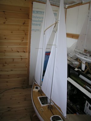
A little more work on the Robbe Atlantis.

The anchor was assembled, and painted matt black, connected up to the winch chain, and hole drilled in deck for the chain hawse hole.. which is actually another eyelet :)

The anchor winch is positioned as per the plan and the the chain threaded through. Don't forget to seal the opening in the deck,with glue or silicone..

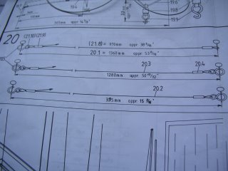
Attention then turned to the handrail section. Holes were marked, and drilled ( 2mm drill bit) as per the plan. I cut up some templates from an old deck strip, in 150mm, 90mm and 60mm lengths, marking up the holes is then easy to do.

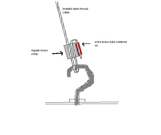
The next stage involves feeding some 1mm brass wire through the lower stanchion holes and cut to length and soldered. However,the fun ( NOT) really starts with the top rail.


For some odd reason ( presumably strength ?) Robbe have supplied 1.5mm spring steel..

This is a ridiculously hard material to a) bend , b) cut and c) solder !
Cutting can only be done with an electric cutting disc... bending requires immense strength... and if you get that far... you won't be able to solder it to the brass stanchions anyway :(


I just don't see the need for this.. so I intend to order some 1mtr lengths of brass rod, to replace the upper railings.

At least , I shall then be able to cut, bend, and solder them !

I shall have to "jump" a little further along with the instructions, until the brass rod arrives.

Steve

Friday, September 22, 2006

Sails

Not much progress this week, due to work etc and usual life "interferences" :(

Have started on drawing in the sail "seams", I think this is really up to the modeller, whether he /she choses to add or not.. Personally I like it... but really it's up to you.

Use a rule and a HB pencil and follow the diagrams.. I used the width of the steel rule for the spaces between the lines.


Take care...

I completely buggered up the top angle of the Gaff Sail.. and pencil ( as I found out)is pretty well permanent, once added to this sail material) So mine does look a bit of a mess close up... ( could kick myself in the butt now ) I havent found anything that will remove it, tried using an eraser, thinnners , kitchen degreaser nothing works...

Oh well......... hopefully it will fade over time...

Then you need to add the sail battens. These are self adhesive plastic that need marking out and cutting to size.

These are "probably" essential, as they add strength to the sail edges and help keep the sails in shape.

Four, 1mm holes need boring/drilling in these, near sail edges.. then stitched with some thread.. more sewing... yuk.

:)

Sunday, September 17, 2006

The Sails

Are pre- made.. all four of them... Other than fitting the strengthening eyelets... to each sail corner.. there's not a lot to do.........


NOW STOP !!!
DO NOT FIT THE EYELETS YET... !!
Despite what the instructions tell you !

Firstly, thread the stay wires into the the seams of the 2 relevant sails.. BEFORE you start to fit the eyelets !

Mark the centre of the seams... I placed a washer in position, then penciled thro the centre .

Then using a heated soldering iron, you burn ( melt) a 3mm hole on each corner.. add a washer, eyelet rivet to one side.. another washer on the opposite side.. peen the rivit over the 2nd washer, which will hold it in position.. ( tis all explained in the instructions)

If, like me you fitted the eyes before threading the darn stay wires through... now is the time to swear !! SO now you will need to remove them.. or struggle your "wotsits" off, trying to thread thewires through !

A tip... the eyelets supplied with servo accessory packs are the right size..

Now just follow the diagrams in the drawings... and you should start to have her looking like a Schooner :)

I still need to do some tweaking to the shrouds..., but couldnt resist adding all the sails to see how she looks :)


More soon !

Steve


Hmm ?

When setting up the masts, I found that the forestay, seemed a little short.. I measured it.. and it is exactly the correct length... however, when placing the 75mm block under the jib boom ( as instructed) I found I couldnt "rake" the forward mast rearwards ( again, as stated in the instructions)

This puzzled me, ( and still does) so I simply added in a small (strong) split ring.. which gave me an extra 1/4 inch or so... and allowed the rake of the masts.

I have no idea where (?) I have evidently lost this length... maybe the brass wire bending too short ? nope... I checked... most odd..

So be warned.. you may be lucky... and not have the problem at all, however, if you do.. there is a solution.

Shrouds continued....


Okay.. so now we have the masts, pretty well completed, time to try and install on the deck..
Hmm.. I failed miserably yesterday... you need the arms of an Octopus to hold things steady, check for vertical and tighten up the shrouds !

Today, I was prepared... after consulting my friend Taylor Sparks...

Firstly, learn from my mistakes... one of these, that is so glaring.. is those deck eye bolts.. to which the mast shrouds attach...

If you have followed the Robbe Atlantis instructions, you will have these screwed in, all the way to the deck... Doh !!


Trust me... unscrew these OUT about a third of their length.. I didn't !!
You will need this adjustment... as I found out.. too late !!

Okay.. so more or less get each mast as vertical as possible... when viewed from the stern.. (unlike this picture.. which shows they need adjustment)

Now I am still, an not happy about the soldering of the steel shrouds, so again, I sought advice.

As the mast shrouds, would appear to take a fair bit of the strain, I chose to secure these, using an idea from Taylor Sparks.. ( rather than the stabilit method I used on the stay wires.


Quite simply... crimp the shrouds in place, one at a time.. then take the loose end of the shroud and thread through an additional brass sleeve ( you will need to supply these) Add flux, and tin this sleeve, as well as the original sleeve with solder..


Now clamp the new sleeve tightly up against the original and solder in situ.. this will effectively secure the shroud in an S bend..


The idea & sketch courtesy of Taylor Sparks. A photo of "one I made earlier" :)


Thursday, September 14, 2006

Shrouds n Stay Wires

Section 20 of the build.. The Stay wires.

Robbe supply a braided stainless steel wire for the stays and shrouds, once cut to length, the ends are assembled with various loops and fittings as per the drawings.

I followed the Robbe instructions to assemble the shrouds. except for the final "fixing". I am reliably informed.. their advised soldering method is, well difficult. As you have two very different material, steel and brass, requiring different fluxes, different temperatures..

As soldering is one of my least favourite elements of ANY modelling..I am not confident adding to my potential failures !

I took the advice of another Robbe Atlantis builder, Colin Harris.

Colin experimented , had success and passed the following information on to me, which I followed.

Use the wood and nail jig as described by Robbe, add the fittings ( loose) to the wire and cut a little over length. Now slide on some heat shrink sleeve, mix up a small qty of Stabilit Express resin.. add to the brass sleeve AND the wires... Tension the wire... then crimp the brass sleeve.

Wipe off the excess, and leave to dry.. You can do several ends at one time to use the resin, before it starts to cure.

When dry, I left overnight, complete the other end, again ,under tension and repeat the above process. Once you are happy with the result, feel free to test it with a vice and pliers.. IT IS VERY , VERY strong.. far more so , than any of my rubbish soldering would have been.

Finally, cut off the excess wire & slip the heat shrink into place .. nice finish.. job done. I shall complete the mast shroud loops in the same way.

My thanks to Colin for the idea :)

Wednesday, September 13, 2006

Booms

Boom preparation is quite straight forward, though I still managed to drill a couple of holes not quite vertically :(

Another thing to watch for is, damage to the aluminium finish when clamping them in the vice for drilling, I thought I had adequately protected them... but sadly they are now marked..SO I may consider rubbing them down and repainting.


The wire bending on two of the booms is made using 1:1 drawings and the 2mm supplied brass rod..

You will find, that the rod is too thick to fit through the swivels that are attached to the booms. I had to drill out the centre to 2.2mm to accept the brass rod.

Similarly, the tops of these fittings are bent over.. however, again you will find the brass rod too wide to fit within the groove of the booms. The only resolution.. here is to open up that groove and file.

This picture from Taylor , shows how its done. ( Thanks Taylor :)


Sunday, September 10, 2006

Frustration Ahead !

Oh dear.. For the first time in this build, my enthusiasm started to wane...

The masts, the shrouds and the booms... :(

Cutting the mast to length is straight forward, the main mast is actually the correct length.

Then comes drilling a multitude of holes.. These really to take some fathoming out from the plans.. some are drilled on one side only, others through both, some from the front.. various offsets too..

I checked, rechecked, checked again.. and still I managed to drill one extra in the wrong place !
This is NOT a job to do if you feel a little under the weather..trust me !

The Shrouds.. are so simple.. but the threading of them thro the lower left hole, up the centre of the mast, then through a brass sleeve , back thro the mast and exit the upper hole on the right hand side...


Sounds easy ?? Dont you believe it !! It has taken me nigh on 3 hours to thread 4 bloomin shrouds !! its the exit thats the problem.

I tried all sorts, pre- threading fishing line, thread, etc thro the upper hole, superglued it to the shroud,,, gently pull back,, nope,, comes off everytime.

In the end I resorted to slightly enlarging the oval hole, and patiently threading the shroud till I could see it over the hole,, then from the opposite side "poked" it with a thin piece of wire.. eventually you will get them,, But incredibly frustrating !!

I had some difficulty, understanding some of the fittings drawings for the mast, I couldn't quite suss the bends of some of the S rings..

I had to ask my good friend Taylor Sparks, http://www.sparksstudios.com/boatyard/atlantis.htm and he kindly took some close up photos of his Robbe Atlantis. Here are the pics, to assist anyone else with this part of the build. :)

Thursday, September 07, 2006

Knitting completed


I am happy with my sheeting endless loop now.. cut the remaining sheets to length, and threaded through the sheet guides to the sliding clamps, and secured with a knot.

All tested and seems to work perfectly :)

That said ... having never used this method of sheet control, it takes a while for "the penny to drop" and understand how the system works..

Once thats mastered, you wonder what all the fuss was about !


Next up is the metal work... the masts and booms.. Section 17 .

I need to study the plans and instructions, in the two masts, there are around 25 holes to be drilled, many different diameters, some even angled... my pillar drill will soon see some action !

Steve

Tuesday, September 05, 2006

Whoops

Well, this evening, I started to fit the endless loop system... boy, this is fun :)
( NOT!)

All my previous and current yachts , use a simple push pull lever arm sail servo.. none of this endless loop stuff.

Followed the instructions ( I think) for the first half of the run, from winch to tensioned pulley and back to aft pulley.

Then my Big Whoops !! oh dear !!

I decided, the servo winch was rotating the wrong way.. so I hit the servo reverse on the computer radio..... Oh no!!!

Streeeetchh.... Boing... lots of Expletives from me...

Why the heck, didnt I disconnect the drum from the winch ??

Servo reversing.. ripped the spring from its housing, after stretching the darn thing by at least 50% .. Oh... Sh*t...

Ah well.. I simply cut it in half, re bent the one end and used that.. presumably the length is not critical... just adds "tension" to the loop system..

After 2 hours mucking about with my knitting, seems I have now "cracked the problem" :)

However, I have had to use the upper and lower EPA ( End Point Adjustments) on the computer radio.. which works a treat.. reduced to 85% and the system "appears" to be now spot on ..

Phew....

SO BEFORE you hit the Winch servo reverse... Disconnect the drum first !!

:) Steve

Sunday, September 03, 2006

Almost time for knitting ?


The sail winch servo assembly was fitted into the hull, after roughing the surface and using Stabilit Express adhesive.

The assembled sheet pulleys were also fitted in situ..


Hmm.. now the " Knitting" lesson beginneth.. Have never dealt with "endless loops" before , this is gonna be fun ! Think I shall need to study the instructions a little more before progressing !


Steve

Slow Ahead


Slow ahead, with this part of the build, no rushing :)

Added the final deck fittings to the aft deck, cleats and sheet guides. Also the fore and aft pin rack frames have been assembled, painted and fitted in place.

Also completed the rudder connection to the servo. I used the supplied linkage, as it is tried & tested, and has built in adjustment. I also re-programmed my radio tx to ATL ( Atlantis) tis great having just one radio tx for up to 6 models... and accessing each models settings at the press of a few buttons :)