Thursday, September 29, 2005

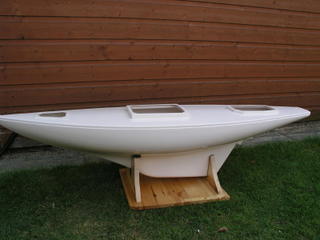
Stabilit at the ready !


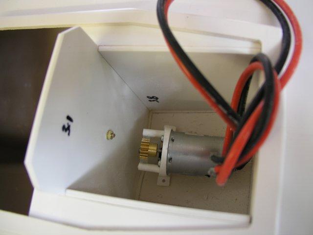
Well, slow ahead progress continues, this pic shows the adaptation of the motor well wall, again with the rudder post parts loose fitted.

As stated earlier, the well, in my case is not a "flooded" compartment, so the cut out is not detrimental to the construction, however it does allow me more space to jiggle the motor set up into a better forward position. Similarly, this cut out allows quite a bit more tiller arm "throw"

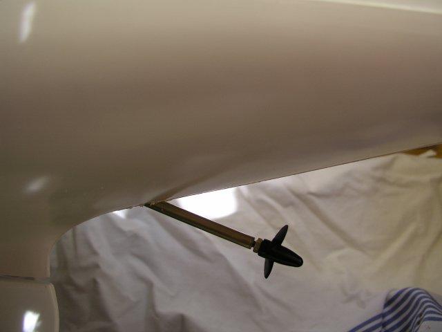
So out with the Stabilit Express ( Recommended by Robbe, and my personal favourite resin adhesive) and glue everything in place, and leave to dry.... After which the motor and popshaft assembly can be glued in situ, check & make sure the propshaft is central along the moulded line on the hull, and there is sufficient clearance for the prop.

Once this stuff sets you will NEVER MOVE IT !!

Tip: line the external part of where the shaft exits the hull with masking tape, this will effectively "mould" the stabilit to the hull shape as it sets,You will need to repeat this excercise, inside and out to make sure the opening is well sealed !


Oh, and before I forget, I drilled a hole in the side wall, to allow the motor wires safe exit, well away from the rotating parts of the motor & gears :)

Monday, September 26, 2005

Knowledge

Posted by Picasa Is such a good thing, and a tip from my friend Taylor Sparks, here. Before finally fixing /gluing the motor well in situ, I thought I'd do a loose, test fit of the rudder stock...As this photo clearly shows, it is very close to that wall!

By the time the tiller arm is on top, I agree with Taylor, that wall will inhibit the "thro" movement of the rudder. Given that this "well" will contain the newer type motor set up, it won't be flooded ( like the old version) so this wall can be trimmed.

I shall make a small cutout, where pencilled, this will allow full movement of the tiller arm, and give me a few mm extra "play" for the motor assembly, should I need it.

Also Taylor suggested that *as built per instructions* he found that single rear pulley position ( you can see its anchor point on that wall) the sheeting loop sometimes interferes with the rudder servo mounting which fits immediately fits in front of the rudder stock.

With this in mind, I have drilled out 2 additional 2.5mm holes which will give me further spacing options, should I need to move the existing & add an additional pulley.

There's no way you would be able to drill those holes, so best do it before its glued in !
Thanks Taylor :)

External View

Posted by Picasa Certainly this new motor set up isn't as discreet as the older drop n lift version. I need to optimise its position before gluing in situ. By moving the motor slightly forward and lowering its angle I could get that prop closer to the hull, however, there is a risk that it would show /break the surface whilst sailing the model.

hmm... I shall think on before adding the glue !

Internal Motor view

Posted by PicasaAs you can see the motor is a tight fit within the motor well /box. Not much rearward movement at all, Immediately behind wall 3.1 there is the rudder post.
I may gain a few mm, if I cut out some of this wall.

Motor fit

Not much progress, to document, other than I started fitting the auxiliary motor set into the hull.
As you can see, the motor well/box needs to be loose fitted, the hull inside is marked with pencil.The dimensions are then marked on the centre line, showing where to drill ( according to the motor set instructions) I used a 6mm drill for a series of holes then opened them up with a small file.

The motor is quite a tight fit inside the box, and the exit angle of the propshaft quite acute.
I shall play with this for a while, to find the optimum position, before gluing n situ.

My friend Taylor Sparks is quite right in his thinking, this "new" type of motor does set the propshaft & propeller higher up the stern centre line , when compared to Robbe's original "drop down "set up.

I have thought of cutting out some of the forward facing wall, this may gain me a couple of mm, but not much, as the rudder post is immediately behind it.

Still, it's got to be fitted........... sometime soon !

HMM...... I am having serious problems uploading images today. I shall continue to try... :(

Seems at the moment the only way I can add pics is to use the Picasa software, personally I'd rather do it manually..

Sunday, September 25, 2005

Men & Women with Atlantis


As I have found so little on the web concerning the Atlantis, owners or builders, I am actively collecting and linking ( with owners permission!) to those sites.

My hope is to provide a resource centre for all of us who own one of these superb models.

You will find my "favourite links" page on my personal site
http://www.busybeas.pwp.blueyonder.co.uk/

is updated as a priority, so do check them often.

It has taken many, many hours, surfing activity to get those few !

However, as in all things, there are" some" losers !

Regrettably " some" I have approached for permission to link have refused, and insisted I remove all traces, fortunately the "true modeller" mostly gives their blessing.

So onward with the research and the build !

Just as a taster, here's a few fab models you can look forward to, ( and the standard I aspire to build to !)


Motor set

These are the parts that make up the newer type of power set, that will be fitted in the "traditional way"

This is the fully assembled unit, expensive I thought, for what is a 380 motor, gears prop shaft , and propellor, but it is tried and tested by Robbe so, it's a "must have".

Under Way

This is really catchup time from my original personal homepages
http://www.busybeas.pwp.blueyonder.co.uk/, But as the build has only recently started it won't take too long :)

The very first part of any build is the building of the stand, the model does need a sturdy base on which it must be built. I "recycled" an old pine desk top for this purpose.


I felt an essential purchase (amongst others), is the Robbe Auxiliary motor /power set. In earlier models Robbe used a cannibalised outboard motor model and it was incorporated inside a flooded, sealed compartment in the hull, and was operated by a lever system and servo which lowered it in and out of the hull !

Personally, I like less water in my model hulls, not more ! Though the idea was a good one.

This method is now no longer available or used, now there is a small motor with gears and traditional propshaft type which is used.

This still fits within the original "motor well" but it is a tight fit, see later diary entry!

This well needs assembly as per the instructions, but it is far too high, and too wide to fit beneath the rear hatch, thus.


After around 2 hours of cutting ,trimming and sanding it does eventually fit. Be warned, you really do need to trim quite a bit off the width and the height.


A little more background

Having found my ISP's webspace allowance a little on the low side, I have now joined the world of "bloggers" :)
This will be a super way to keep track of the progress of my latest model, The Atlantis,

Here's a little more info from Robbe, the kit manufacturers, which will give you some idea of the scale of this build!


The models details taken from the http://www.robbe.com/ site,

Twin-masted Gaff Schooner to 1:20 scaleThe original vessel was built in 1935 and is a 28 m long gaff-rigged schooner. The special sail arrangement on the boat makes her stand out from the more familiar ship types of her time, and for this reason she is of particular interest to the modeller. With a sail area of just on one square metre, distributed over several separate sails, and a streamlined hull with its characteristic extended keel, this imposing model offers an excellent performance and good manoeuvring capability. Although the boat is quite heavy, the draught of the Atlantis is relatively small, so shallow in-shore waters present no problem. The multiple sails give the operator plenty of scope for trimming the model to suit different wind speeds just by lowering and setting individual sails. For light winds a Genoa is available. The boat features an ingenious tensioning mechanism which means that only one screw has to be slackened on each mast when it is time to transport the "Atlantis". All the shroud settings can be left unchanged.

The Beginning, the kit


The Kit is packed in a HUGE box,some 5 feet by 18"square, just about fits within my car with seats folded down!

I had to "come clean" with the wife on this purchase, it's rather too large to smuggle in !

It's certainly not a cheap model, when one adds accessories ( rather essentials to my mind) but £'s per inch, it compares rather well to other models ( I am still TRYING TO CONVINCE THE WIFE !)

Inside, the contents are of excellent quality, the Robbe "Plura" moulded hull is superb, with precut hatches, and rudder post hole pre-drilled, and is of consistent thickness throughout.

Though it is a type of abs plastic, it is not to be confused with cheaper thinner "efforts" from other manufacturers.

The quality, even puts to shame some of the better g/f hulls I have experienced to date !